IGMIN: We're glad you're here. Please click 'create a new query' if you are a new visitor to our website and need further information from us.
If you are already a member of our network and need to keep track of any developments regarding a question you have already submitted, click 'take me to my Query.'
Welcome to IgMin Research – an Open Access journal uniting Biology, Medicine, and Engineering. We’re dedicated to advancing global knowledge and fostering collaboration across scientific fields.
At IgMin Research, we bridge the frontiers of Biology, Medicine, and Engineering to foster interdisciplinary innovation. Our expanded scope now embraces a wide spectrum of scientific disciplines, empowering global researchers to explore, contribute, and collaborate through open access.
Welcome to IgMin, a leading platform dedicated to enhancing knowledge dissemination and professional growth across multiple fields of science, technology, and the humanities. We believe in the power of open access, collaboration, and innovation. Our goal is to provide individuals and organizations with the tools they need to succeed in the global knowledge economy.
IgMin Publications Inc., Suite 102, West Hartford, CT - 06110, USA
Reconstruction of pulverized coal boilers BKZ (Barnaul Boiler Plant, steam productivity 160 t/h, pressure 100 kgf/cm2, fuel: natural gas/fuel oil) with steam productivity of 160 t/h, converted to gas combustion, and an increased load capacity to 210 t/h, has been carried out. As part of the boiler modernization, a chemical water treatment system was reconstructed, significantly improving the quality of feedwater: hardness not exceeding 0.3-0.5 µeq/kg; SiO2 not exceeding 18 µg/kg, and electrical conductivity Х=0.6-1.0 µS/cm. The previously used phosphate regime for boiler water was replaced with a chelant-based regimen using trilon B. During operation, widespread damage to the screen tubes occurred. Circulation tests were conducted on one of the boilers, and an analysis of internal deposits was performed.
It was determined that water circulation in the side screen is stable, and its velocities correspond to calculated values. The main cause of metal ruptures in the screen tube is metal corrosion, as well as local overheating of the wall caused by the formation of a steam layer due to the detachment of internal deposits.
At one of the power plants in Kazakhstan, a reconstruction project by OAO “Sibenergomash” was implemented for two pulverized coal boilers BKZ with a steam productivity of 160 t/h [1], converted to gas combustion, and an increased load capacity to 210 t/h.
The open-type combustion chamber, constructed in a gas-tight design during reconstruction, has a prismatic shape and dimensions of 4416×7104 mm along the axis of the tubes. The walls of the furnace are shielded with panels made of 60×6 mm pipes, steel 20, with an 80 mm pitch, and a strip welded between them.
The boiler operates with natural circulation, a steam pressure of 10.0 MPa, and a superheating temperature of 520 °C. It is a single-drum boiler with a P-shaped arrangement.
The combustion chamber is equipped with 6 swirl-type gas-oil burners located on the front screen of the boiler in three tiers at elevations: +4.70 m, +6.8 m, and +8.9 m. The boiler drum, with an internal diameter of 1600 mm, has a wall thickness of 89 mm and is made of 22K steel. The cylindrical part of the drum has a length of 10300 mm.
To achieve the required steam quality in the boiler, a two-stage evaporation scheme is employed. In the first evaporation stage (clean section), a steam-water mixture from the front and rear screen panels, as well as from the front panels of the side screens, enters. Separation devices for the first evaporation stage are implemented in the form of cyclones arranged in two rows in the boiler drum. Steam, after passing through the intra-drum cyclones, goes through a bubbling and washing device and is directed to the superheater.
The steam-water mixture from the rear panels of the side screens (salt section) is directed to external cyclones, where steam separation occurs, and it is also directed to the superheater. External cyclones are made of pipes with a diameter of Ø 426/30 mm, arranged in two cyclones on each side wall of the boiler. The length of the external cyclones compared to the project solution is increased by 400 mm.
The open-type combustion chamber, constructed in a gas-tight design during reconstruction, has a prismatic shape and dimensions of 4416×7104 mm along the axis of the tubes. The walls of the furnace are shielded with panels made of 60×6 mm pipes, steel 20, with an 80 mm pitch, and a strip welded between them.
In the lower part of the furnace, the front and rear screens form a double-sloped bottom, made without refractory coating, with an inclination angle of 28° to the horizontal.
The circulation scheme of the reconstructed boiler is nearly identical to the project design. The difference lies in a 25% reduction in the total number of evaporator tubes due to a decrease in the spacing between them.
The conducted circulation calculations demonstrate the compliance of all screen reliability indicators with regulatory values.
During the boiler modernization, a reconstruction of the chemical water treatment system was carried out, significantly improving the quality of feedwater: hardness not exceeding 0.3-0.5 µeq/kg; SiO2 not exceeding 18 µg/kg, and electrical conductivity Х=0.6-1.0 µS/cm. The previously used phosphate regimen for boiler water was replaced with a chelant-based regimen using trilon B.
In the course of operation, almost simultaneously, both boilers experienced widespread damage to the screen tubes. Boiler No. 5 had an operating time of 27,000 hours, while Boiler No. 4 had 16,000 hours. The boilers operated with a load of 120-180 t/h.
The damages occurred exclusively on 14 screen tubes of the left and right side screens, located at the angular panels towards the rear screen, supplied with boiler water from the second external cyclone, effectively serving as the third evaporation stage.
The damages were observed in the form of numerous leaks and metal ruptures on the fire side of the tubes at elevations of 5-15 meters.
Therefore, a replacement of screen tubes was carried out on both side screens, totaling 14 tubes.
This article aims to identify and describe the primary causes of metal fractures in screen tubes, associated with metal corrosion, as well as localized wall overheating caused by the formation of a steam layer due to the detachment of internal deposits.
The power plant management speculated that the damage to the screen tubes was caused by a disruption in the water circulation in the screens. It was suggested to conduct circulation tests on one of the boilers.
For this purpose, Pitot tubes manufactured by OAO “NPO CKTI” were installed on the screen tubes (134, 139, 141 of the third evaporation stage and tube 128 of the second evaporation stage of the right side screen), as well as temperature probes.
The circulation velocity in the screen tube is determined by the formula:
where k - is the coefficient of head loss in the tube; ΔP - is the dynamic pressure of the flow as indicated by the secondary device, Pa; ρ - is the density of the medium, kg/m3.
Temperature sensors also allow determining the heat load at the installation point using the formula:
where T1 - is the outer wall metal temperature, °C; T2 - is the saturation temperature at the sensor installation point, °C; β - is the ratio of the outer and inner diameters of the tube at the thermocouple sealing point; µ - is the heat dissipation coefficient; s - is the thickness of the tube at the thermocouple sealing point, m; λm - is the thermal conductivity coefficient of the tube metal, kcal/(m·h·°C); α2 - is the coefficient of heat transfer from the inner surface of the tube wall to the environment, kcal/(m2·h·°C).
The registration of dynamic pressure and metal temperatures was carried out on the computer of the station’s DCS.
Inserts, manufactured by OAO “NPO CKTI,” for measuring the temperature on the outer surface of the screen tubes from the fireside were installed around the furnace at elevations:
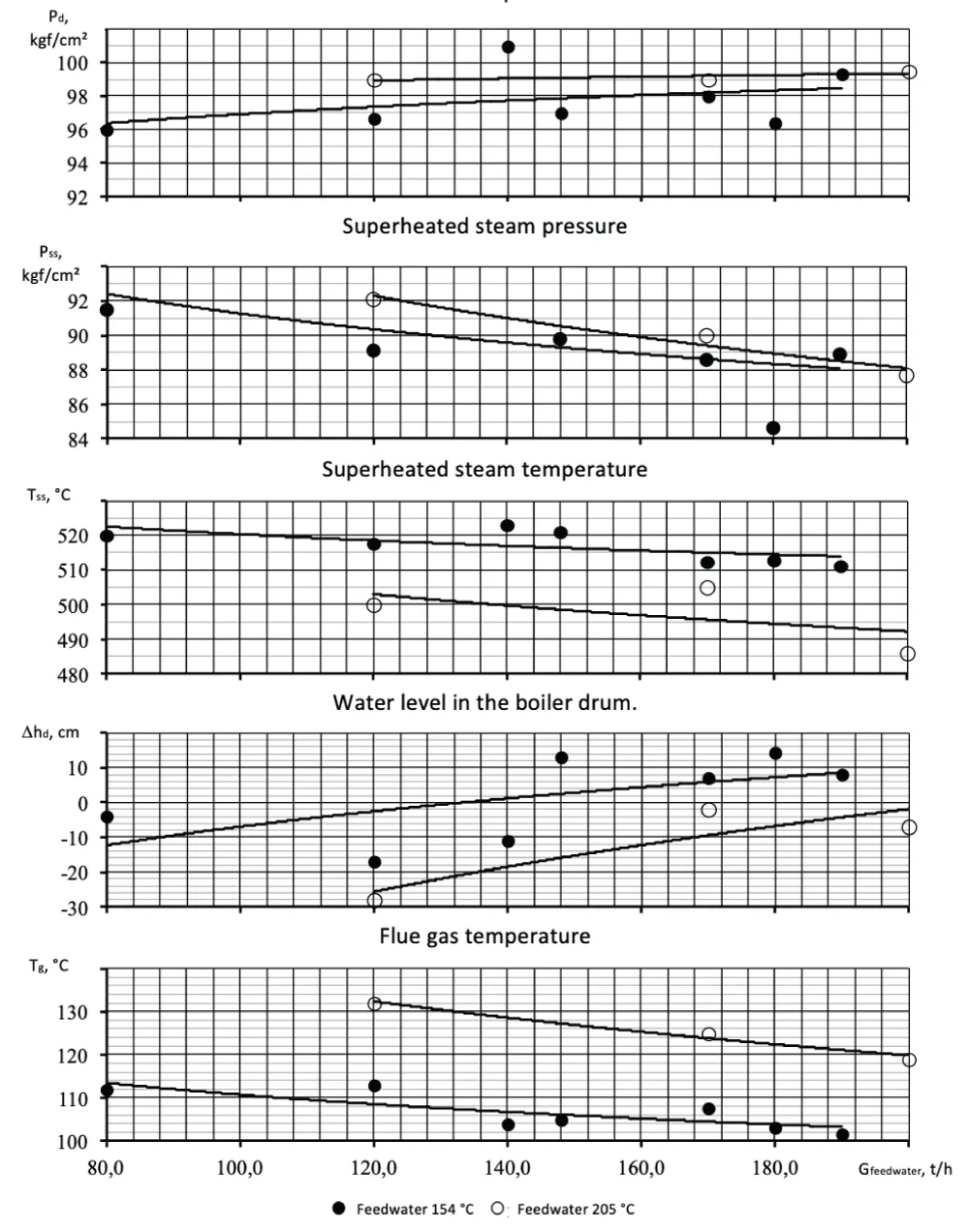
Figure 1 presents the test results of the boiler in the load range of 190-200 t/h. From the figure, it can be seen that circulation velocities slightly increase with the load, from 1.0 m/s at a load of 120 t/h to 1.3 m/s at a load of 200 t/h, and their values practically correspond to the calculated values.
Figure 1: Main parameters of the boiler and circulation velocities with changes in boiler load Boiler drum pressure.
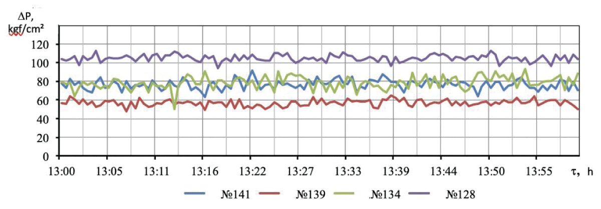
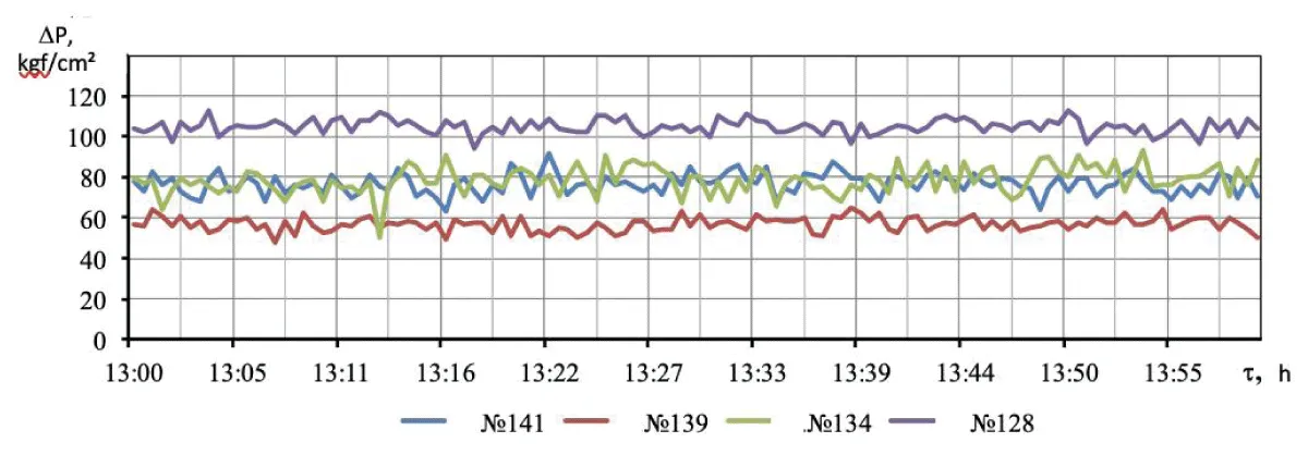
Figure 2 shows the change in dynamic pressure of Pitot tubes at a load of 190 t/h, indicating that circulation velocities have minor structural pulsations and exhibit a stable character.
Figure 2: Dynamic pressure of Pitot tubes at a boiler load of 190 t/h and feedwater temperature of 205 °C.
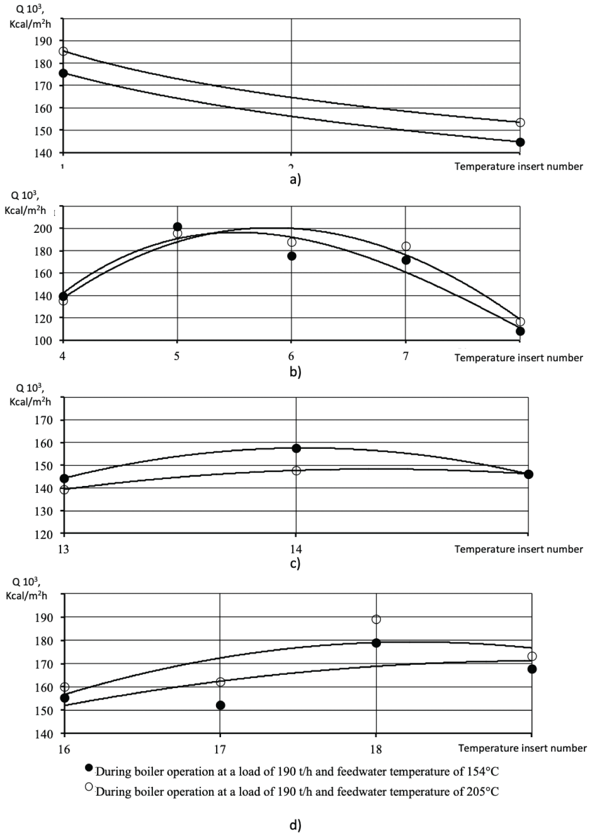
As seen in Figure 3, which illustrates the distribution of heat flows across the width of the left side screen, the maximum heat flows do not exceed 200,000 kcal/m2h. At such heat load values and measured circulation velocities, the occurrence of critical deterioration of heat transfer in the screen tubes is excluded, which is confirmed by temperature measurements on the outer surface of the screen tubes, with values not exceeding 330 °C - 345 °C.
Figure 3: Distribution of heat loads across the width of the furnace at an elevation of 8.0 m. a) Front screen; b) Right side screen; c) Rear screen; d) Left side screen.
Unfortunately, it was not possible to provide a boiler load exceeding 200 t/h due to the operation of the induced draft devices.
Thus, it can be stated that water circulation in the side screen is stable and its velocities correspond to calculated values, which cannot be the cause of screen tube damage.
During emergency boiler shutdowns, an imbalance in the feedwater and superheated steam flow of 25-30 t/h is typically observed due to the rupture of the screen tube and the presence of numerous leaks (25-30 pieces).
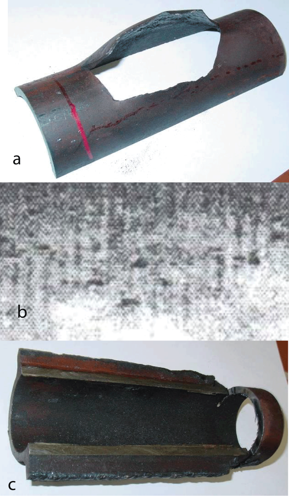
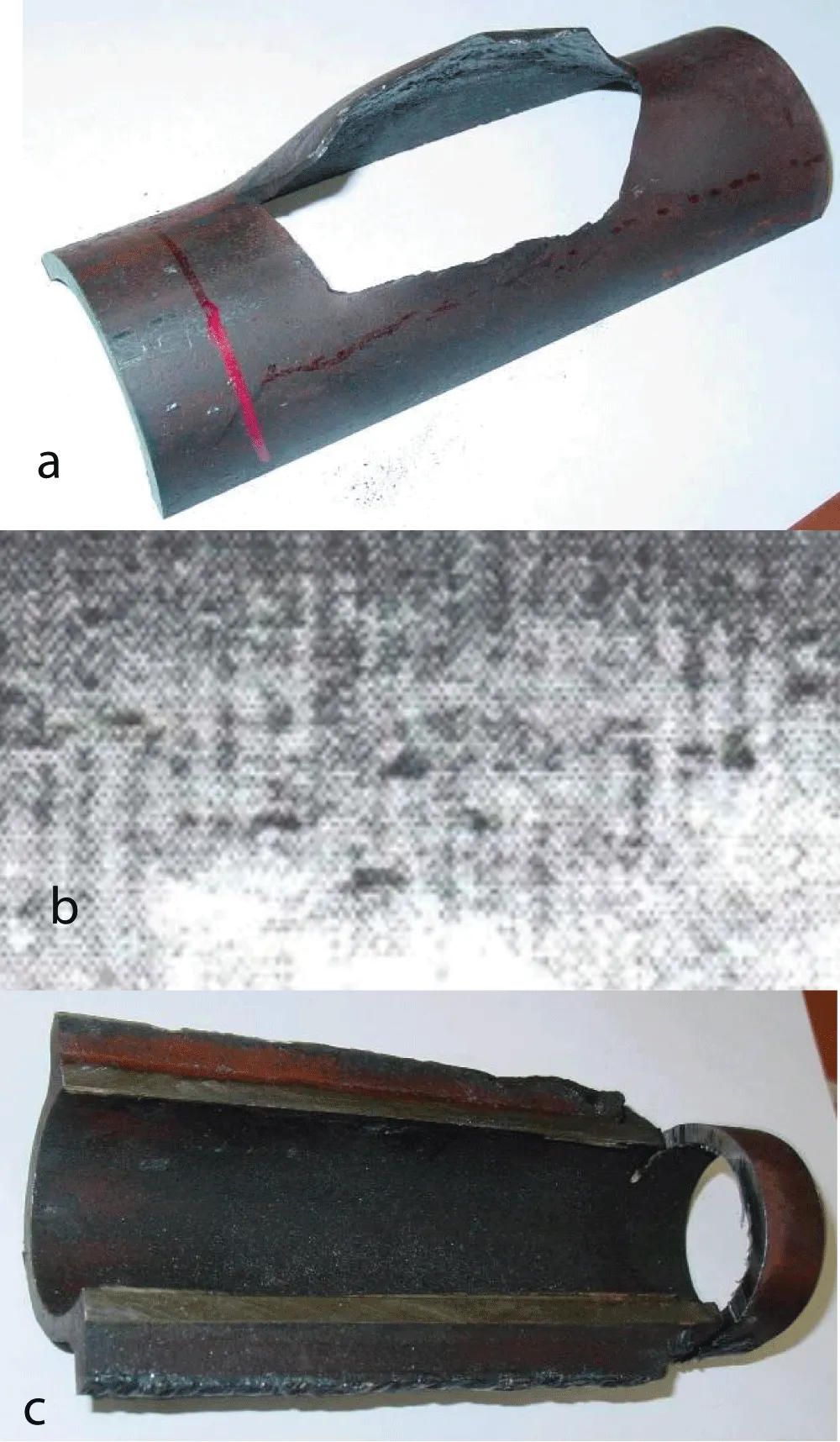
Figure 4 presents photographs of the damaged screen tube. The damage is characterized by metal rupture on the heated side. On the internal fire side of the tube, the damaged metal is subject to significant corrosion. Traces of point corrosion, in the form of ulcers with a diameter of 1.2 mm - 3 mm and a depth of no more than 0.5 mm, are observed on the internal surface of the back side of the tube.
Figure 4: Photograph of a damaged tube. Here, a) Fire half of the tube; b) Internal surface of the fire half of the tube; c) Internal surface of the back half of the tube.
On the internal surface of the fire half of the tube, there are dense black deposits, amounting to 176 g/m2, determined by the cathodic etching method and consisting mainly of iron oxides (75% - 90% Fe2O3). Significant losses during annealing (up to 8%) are noted.
Internal deposits on the fire side of the tube are solid and practically cannot be removed by mechanical means, while on the back side, they are loose and easily removable by mechanical scraping.
Table 1 provides the chemical composition of the main elements of the screen tube, indicating that their content corresponds to steel 20 according to TU 14-3R-55-01. The brief mechanical characteristics of the tube metal, presented in Table 2, also comply with TU 14-3R-55-01.
Table 1: Chemical composition of the main elements of the metal of the BKZ-160-100GM boiler tube.
Chemical Composition of Main Elements, %
C
Si
Mn
Cr
Ni
Mo
V
Cu
S
P
Actual Composition
0.21
0.17
0.45
0.02
0.02
-
-
0.11
0.015
0.018
Requirements per TU 14-3R-55-01 for Steel 20
0.17-0.24
0.17-0.37
0.35-0.65
≤ 0.25
≤ 0.25
-
-
≤ 0.30
≤ 0.025
≤ 0.030
Table 2: Mechanical properties at room temperature of a cutout from the tube metal of the BKZ-160-100GM boiler.
Examined Tube Section
σv (kgf/mm²) at 200 °C
σ0.2 (kgf/mm²) at 200 °C
δ (%) at 200 °C
NV
In the zone of local thinning
-
-
-
145
Section of the tube outside the damage zone
46.9
46.0
32.2
137-141
TU 14-3-460 (TU 14-3R-55-01) Requirements for Steel 20 Tubes
42.0-56.0
≥ 22.0
≥ 24.0
-
The formation of numerous leaks, in the form of through holes with a diameter of 0.5 mm - 1.0 mm, is caused by internal corrosion of the metal due to the destruction of the protective film, resulting from the impact of aggressive boiler water. Metal overheating in the area of leaks is not observed.
The main cause of metal ruptures in the screen tube (Figure 3a), with dimensions of 120x40 mm, is metal corrosion, as well as local overheating of the wall caused by the formation of a steam layer due to the detachment of internal deposits.
Damage to only 14 screen tubes, supplied with water from the second external cyclone, is due to the elevated concentration of salts in the boiler water. In studies [2-4], it is shown that despite the presence of a common collector at the entrance to the screen tubes of the salt evaporation stage, constructed with the sequential inclusion of external cyclones, the salt content in the boiler water from the second external cyclone, which supplies water to the 14 damaged tubes, is approximately 3-4 times higher than in tubes of the adjacent panel.
During prolonged operation of the boilers with phosphate treatment of boiler water, internal deposits were formed, which were not removed by chemical flushing before transitioning to trilon VHR. When trilon B was introduced, the dissolution of deposits and a change in their structure occurred, forming dense corrosive compounds in the tubes of the third evaporation stage.
Due to the difference in thermophysical properties between changed deposits and tube metal, their delamination occurred, creating a steam layer at the tube wall, where deep evaporation of salts and intensified corrosion, as well as metal overheating, took place. It is worth noting that similar types of screen tube damage were observed in boilers with direct combustion.
After the replacement of the screen tubes, no damages were observed on the reconstructed boilers.
The study determined that water circulation in the side screen is stable, and its velocities correspond to calculated values. The main cause of metal ruptures in the screen tube is metal corrosion, as well as local overheating of the wall caused by the formation of a steam layer due to the detachment of internal deposits.
Address Correspondence: MS Popov, Joint-Stock Company “I. I. Polzunov Scientific and Development Association on Research and Design of Power Equipment” JSC “NPO CKTI”, St. Petersburg, Russia, Email: [email protected]
How to cite this article: Popov M, Belyakov I, Tolstyh A. Analysis of Damages to Boiler Screen Tubes BKZ-160-100-GM (Barnaul Boiler Plant, steam productivity 160 t/h, pressure 100 kgf/cm2, Fuel: Natural Gas/Fuel Oil) after Reconstruction for Increased Steam Productivity to 210 t/h. IgMin Res. 15 Apr, 2024; 2(4): 218-223. IgMin ID: igmin168; DOI:10.61927/igmin168; Available at: igmin.link/p168


 Scan and get link